This article will discuss a new approach for Azure Data Factory (ADF) or Synapse Analytics (ASA) to leverage the Microsoft Graph API for accessing and integrating with various Microsoft 365 services and data. Examples include ADF downloading files from SharePoint (SPO) to Azure Data Lake Storage (ADLS), creating folders in SharePoint libraries, and moving files between SharePoint folders.
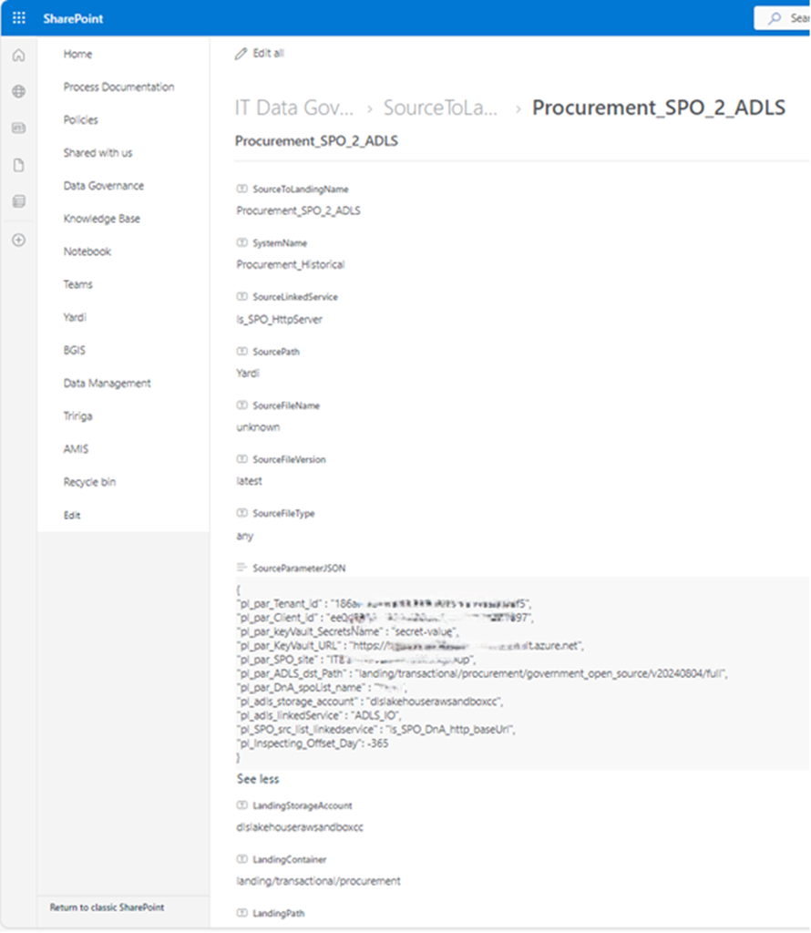
We’ve previously discussed using Azure Data Factory (ADF) or Synapse Analytics (ASA) to download files from SharePoint to Azure Data Lake Storage (ADLS) Gen2. Specifically, we explored a metadata-driven approach for incrementally copying data from SharePoint Online to ADLS Gen2.
I recently received reports indicating that our previous method for downloading files from their SharePoint Online (SPO) environment is no longer working. Upon investigation, I confirmed that changes to the configuration of some SharePoint sites prevent the standard download solution from functioning.
What is Microsoft Graph API.
The Microsoft Graph API is a unified RESTful web API provided by Microsoft that allows developers to access and integrate with a wide range of Microsoft 365 services and data. This includes data from:
- Azure Active Directory (Entra ID)
- Outlook (Mail, Calendar, Contacts)
- OneDrive and SharePoint
- Teams
- Excel
- Planner
- Intune
- To Do, and many others.
Scenario
At Mainri Corporation, colleagues upload files to a designated folder on their SharePoint site. As part of their data centralization process, files from a shared SharePoint Online folder named “Current” are copied to ADLS. Once the copy is successful, these files are then relocated from the “Current” folder to an “Archive” folder within the same SPO Library.
For this purpose, let’s utilize the mainri SharePoint Online (SPO) site, ‘IT-BA-site’ (also known as ‘IT Business Partners’), along with its dummy library and folders. The library’s name is ‘Finance’.
There are multiple folders under the Finance Library, colleagues upload file to:
Finance/Business Requests/AR Aging Report/Current.
The Archive folder is: Finance/Business Requests/AR Aging Report/Archive .

Prerequisites:
An Azure AD Application (AAD) Registration with Microsoft Graph API permissions.
Because SharePoint is a protected Microsoft 365 service, ADF cannot access it directly. So you:
- Register an AAD App
- Assign it permission to read SharePoint files (
Sites.Read.All,Files.Read.All) - Use the AAD App credentials (client ID, secret, tenant ID) to obtain an access token
- Pass that token to Microsoft Graph API from ADF pipelines (using Web Activity + HTTP Binary Dataset)
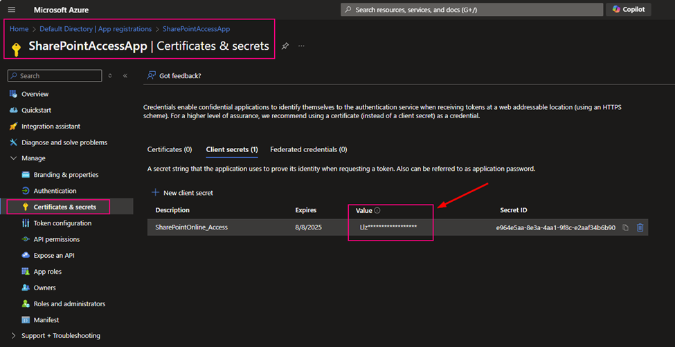
Register an Azure Active Directory Application (AAD App) in Azure
- Go to Azure Portal > Azure Active Directory > App registrations.
- Click “New registration”.
- Name:
ADF-GraphAPI-App - Supported account types: Single tenant.
- Name:
- Click Register.
we want to get:
- Client ID: Unique ID of your app — used in all API calls
- Tenant ID: Your Azure AD directory ID
- Client Secret: Password-like value — proves app identity
- Permissions: Defines what APIs the app is allowed to access
Grant Graph API Permissions
Go to the API permissions tab.
Click “Add a permission” > Microsoft Graph > Application permissions.
Add these (at minimum):
- Sites.Read.All – to read SharePoint site content.
- Files.Read.All – to read files in document libraries.
Click “Grant admin consent” to enable these permissions.
Solution
The ADF major steps and activities are:
Register an Azure AD Application (if not using Managed Identity), Grant the application the necessary Microsoft Graph API permissions, specifically Sites.Selected.
Enable Managed Identity for your ADF (Recommended), Grant the ADF’s managed identity the necessary Microsoft Graph API permissions, specifically Sites.Selected. Enable Managed Identity for your ADF (Recommended), Grant the ADF’s managed identity the necessary Microsoft Graph API permissions, specifically Sites.Selected.
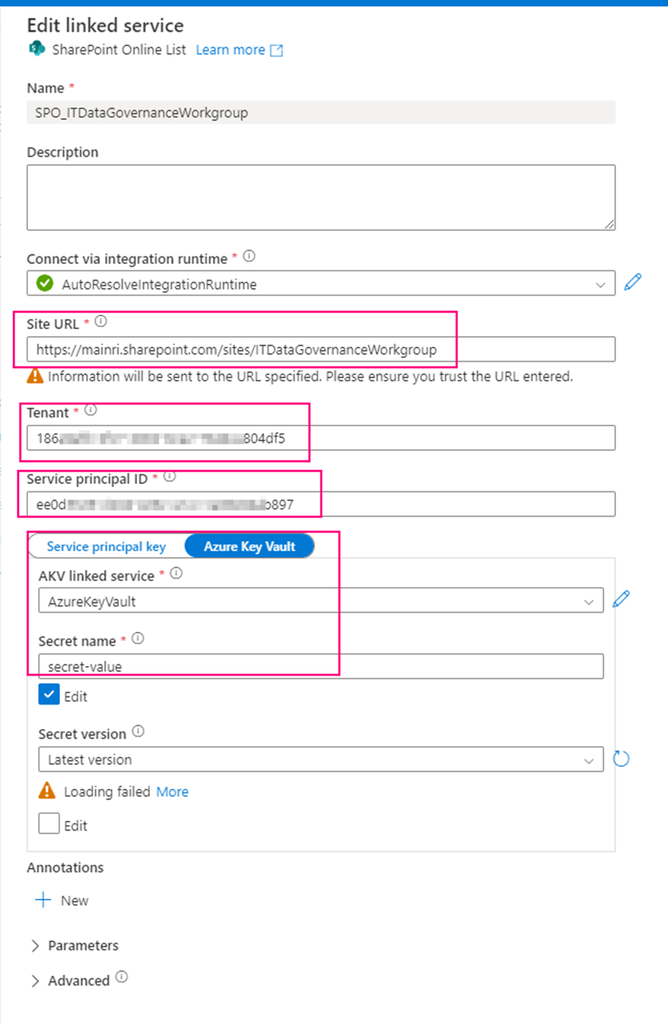
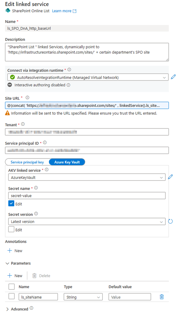
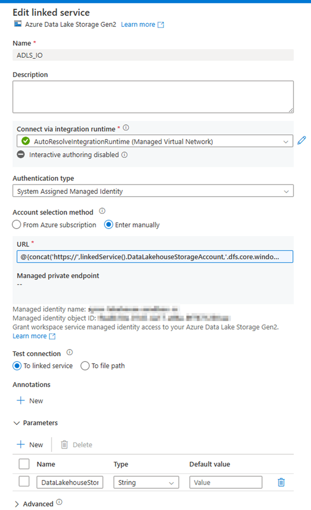
Create a HTTP Linked Service in ADF,
Base URL:
https://graph.microsoft.com/v1.0
Web Activity to get an access token
URL: https://login.microsoftonline.com/<your_tenant_id>/oauth2/token
Method: POST
Body: (for Service Principal authentication)
JSON
{
"grant_type": "client_credentials",
"client_id": "<your_application_id>",
"client_secret": "<your_client_secret>",
"resource": "https://graph.microsoft.com"
}
Authentication: None Headers:Content-Type: application/x-www-form-urlencoded
Web Activity to get the Site ID
URL:https://graph.microsoft.com/v1.0/sites/<your_sharepoint_domain>:/sites/<your_site_relative_path>(e.g., https://mainri.sharepoint.com:/sites/finance)

Method: GET

Authentication: none

header: "Authorization"
@concat('Bearer ', activity('<your_get_token_activity_name>').output.access_token).
Web Activity to list the drives (document libraries)
URL: @concat('https://graph.microsoft.com/v1.0/sites/', activity('<your_get_site_id_activity_name>').output.id, '/drives')
Method: GET

Authentication: none

header: "Authorization"
@concat('Bearer ', activity('<your_get_token_activity_name>').output.access_token).
Web Activity (or ForEach Activity with a nested Web Activity) to list the items (files and folders) in a specific drive/folder:
URL: @concat('https://graph.microsoft.com/v1.0/drives/', '<your_drive_id>', '/items/<your_folder_id>/children') (You might need to iterate through folders recursively if you have nested structures).

Method: GET

Authentication: none

header: "Authorization"
@concat('Bearer ', activity('<your_get_token_activity_name>').output.access_token).
Copy Activity to download the file content
Source: HTTP Binary
Relative URL: @item()['@microsoft.graph.downloadUrl']
method: GET
Sink: Configure a sink to your desired destination (e.g., Azure Blob Storage, Azure Data Lake Storage). Choose a suitable format (Binary for files as-is).
Finally, Web Activity move processed file to Archive area.
URL: https://graph.microsoft.com/v1.0/drives/<your_drive_id>/items/<your_file_item_id>

Method; PATCH

Body:
@json(
concat(
' { "parentRefence": {'
, ' "id":" '
, activity('Create_rundate_folder_under_archive').output.id
, ' "}}'
))
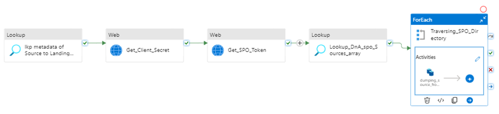
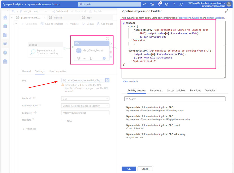
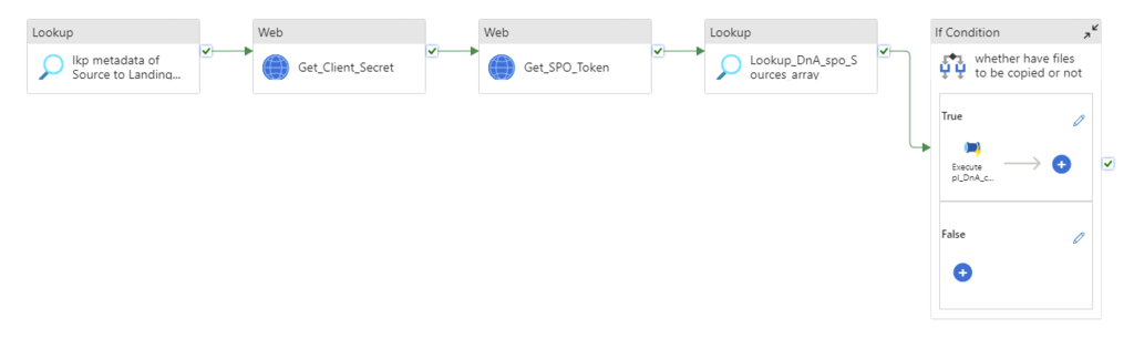
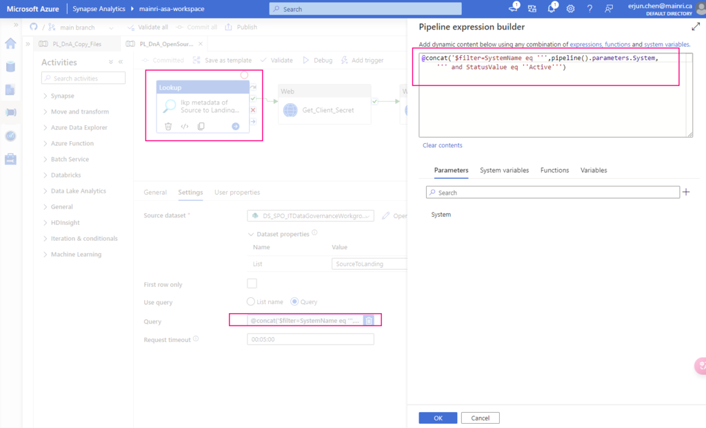
Step 1: Get Client Secret from Azure Key Vault
Web activity
purpose: get client secret that saves in Azure Key Vault.

Url: @{concat(
         pipeline().parameters.pl_par_KeyVault_URL
        , '/secrets/'
        , pipeline().parameters.pl_par_keyVault_SecretsName
        , '?api-version=7.0'
)}

Method: Get
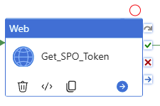
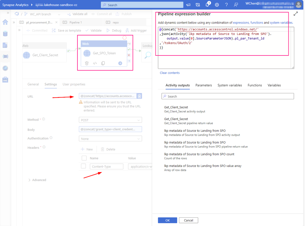
Step 2: Get SPO access Bearer Token
Web activity
purpose: all Graph API have to use the Bearer access token

URL:
@concat(
    'https://login.microsoftonline.com/'
    , pipeline().parameters.pl_par_Tenant_id
    , '/oauth2/v2.0/token'
)

Method: POST

Body:
@concat(
  'client_id=', pipeline().parameters.pl_par_Client_id,
  '&client_secret=', activity('Get_Client_Secret').output.value,
  '&grant_type=client_credentials',
  '&scope=https://graph.microsoft.com/.default'
)

Header: Content-Type : application/x-www-form-urlencoded

The response has expires_in and ext_expires_in
expires_in: This tells you how many seconds the access token is valid for — in your case, 3599 seconds (which is just under 1 hour). After this time, the token will expire and cannot be used to call the Graph API anymore.
ext_expires_in: This is the extended expiry time. It represents how long the token can still be accepted by some Microsoft services (under specific circumstances) after it technically expires. This allows some apps to use the token slightly longer depending on how token caching and refresh policies are handled.
For production apps, you should always implement token refresh using the refresh token before expires_in hits zero.
Save the token in a variable, as we will use it in subsequent activities.
Set variable activity
Purpose: for following activities conveniences, save it in a variable.

@activity('GetBearerToken').output.access_tokenStep 3: Get SPO site ID via Graph API by use Bearer Token
Sometime your SharePoint / MS 365 administrator may give you SiteID. If you do not have it, you can do this way to get it.
Web activity
purpose: We will first obtain the “site ID,” a key value used for all subsequent API calls.

URL:
@concat('https://graph.microsoft.com/v1.0/sites/'
, pipeline().parameters.pl_par_Tenant_name
,'.sharepoint.com:/sites/'
, pipeline().parameters.pl_par_SPO_site
)

Method: GET

Header:
Authorization
@concat('Bearer ',activity('GetBearerToken').output.access_token)
output segments:
{ ….
“id”: “mainri.sharepoint.com,73751907-6e2b-4228-abcd-3c321f3e00ec,bee66b00-7233-9876-5432-2f0c059ec551″,
….}
from the output, we can see that ID has 3 partitions. the entire 3-part string is the site ID. It is a composite of:
- hostname (e.g.,
mainri.sharepoint.com) - site collection ID (a GUID)
- site ID (another GUID)

Step 4: Get SPO Full Drivers list via Graph API by use Bearer Token
“Driver” also known as Library.
Web activity
purpose: Since there are multiple Drivers/Libraries in the SPO, now we list out all Drivers/Libraries; find out the one that we are interested in – Finance.

Url:
 @concat('https://graph.microsoft.com/v1.0/sites/'
, activity('GetSiteId').output.id
, '/drives')

Method: GET

Header: Authorization: @concat('Bearer ',activity('GetBearerToken').output.access_token)


Step 5: Filter out our interested Library “Finance” via Graph API by use Bearer Token
Filter Activity
Purpose: Find out the Finance’s ID.
Since there are multiple drivers/Libraries in the SPO, we are interested in the “Finance” only

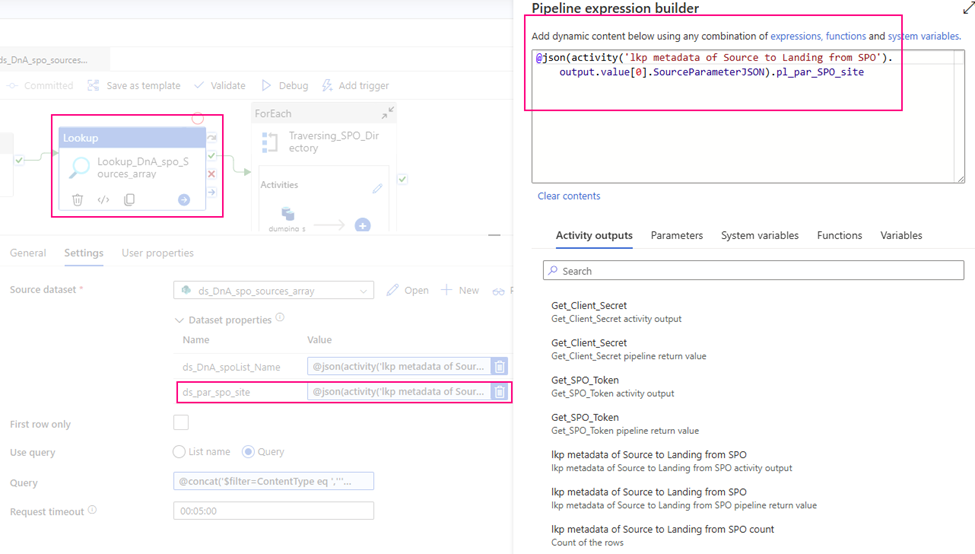
Items:@activity('GetFullDrives').output.value
Condition: @equals(item().name, 'Finance')
Output Segments

Save the DriverID/LibraryID in a variable.
We will use the LibraryID/DriverID in the following activities, so save it for convenience.
Step 6: Use the Bearer Token with the Graph API to retrieve a list of subfolders in the Finance library’s root.
Web Activity
Purpose: Navigate to the ‘Business Request’ folder in the Finance library’s sub-folders and retrieve its ID.

URL:
@concat('https://graph.microsoft.com/v1.0/drives/'
, activity('FilterFinance').output.value[0].id
, '/root/children')

Method: GET

Header: Authorization
@concat('Bearer ',activity('GetBearerToken').output.access_token)
Output segment

Step 7: Find the ‘Business Request’ sub-folder under ‘Finance’.
Filter activity
Purpose: Find out folder “Business Request” ID

Items: @activity('Get_FinanceRoot').output.value
Condition: @equals(item().name, 'Business Requests')
output segments

Step 8: Get “Business Request” child items via Graph API
Check the sub-folders within ‘Business Request’ and identify the one titled ‘AR Aging Report’, as that is our focus
Web Activity
Purpose: Get ‘Business Request’ child items using Graph API.

URL:
@concat('https://graph.microsoft.com/v1.0/drives/'
, activity('FilterFinance').output.value[0].id
, '/items/'
, activity('FilterBusinessRequest').output.value[0].id
, '/children'
)

Method: GET

Header:
Authorization: @concat('Bearer ',activity('GetBearerToken').output.access_token)
output segments

Step 9: Filter out sub-folder “AR Aging Report” from Business Request via Graph API
Filter Activity
Purpose: Maybe, there are multiple child items under this folder. We are interested in the “AR Aging Report” and its ID only.

Items: @activity('GetBusinessRequests_Children').output.value
Condition: @equals(item().name, 'AR Aging Report')
output segment

Step 10: Get “AR Aging Report” child items list
Web Activity
Purpose: We require the folder IDs for the “Current” folder (where colleagues upload files) and the “Archive” folder (for saving processed data), as indicated by the business, to continue.
— “Current” for colleagues uploading files to here
— “Archive” for saving processed files

URL:
@concat('https://graph.microsoft.com/v1.0/drives/'
, activity('FilterFinance').output.value[0].id
, '/items/'
, activity('Filter_AR_Aging_Report').output.value[0].id
, '/children'
)

Method: GET

Header:
Authorization : @concat('Bearer ',activity('GetBearerToken').output.access_token)
output segments


Step 11: Find the ‘Current’ folder under ‘AR Aging Report’
Filter Activity
Purpose: Find out the “Current” folder that saves uploaded files

Items: @activity('Get AR Aging Children').output.value
Condition: @equals(item().name, 'Current')
output segments

Save the Current folder ID in variable
for following activities convenience, save the “Current” folder ID in a variable.

Value: @activity('Filter_Current').output.value[0].idStep 12: Obtain a list of all files within the ‘Current’ folder.
Web Activity
Purpose: Retrieve a list of files from the ‘Current’ folder to be copied to ADLS.

URL:
@concat('https://graph.microsoft.com/v1.0/drives/'
, activity('FilterFinance').output.value[0].id
, '/items/'
, activity('Filter_Current').output.value[0].id
, '/children'
)

Method: GET

Header: Authorization: @concat('Bearer ',activity('GetBearerToken').output.access_token)
Step 13: Check if today’s folder exists.
If condition Activity
Purpose: To check if a folder for today’s date (2025-05-10) already exists and determine if a new folder needs to be created for today’s archiving.

Expression:
@greater(
    length(activity('Get_Current_Files').output.value)
    ,1
)
Within the IF-Condition activity “True” activity, there more actions we take.
Since new files are in ‘Current’, we will now COPY and ARCHIVE them.
- Find out “Archive” folder, then get the Archive folder ID
- List out all child items under “Archive” folder
- Run ‘pl_child_L1_chk_rundate_today_exists’ to see if ‘rundate=2025-05-12’ exists. If so, skip creation; if not, create ‘rundate=2025-05-12’ under ‘Archive’..
- Get all items in ‘Archive’ and identify the ID of the ‘rundate=2025-05-13’ folder.
- Then, run ‘pl_child_L1_copy_archive’ to transfer SPO data to ADLS and archive ‘current’ to ‘Archive/rundate=2025-05-12’.
Begin implementing the actions outlined above.
We begin the process by checking the ‘Current’ folder to identify any files for copying. It’s important to note that this folder might not contain any files at this time.
Step 14: Inside the ‘chk-has-files’ IF-Condition activity, find the ID of ‘Archive’ using a filter.
Filter activity
Purpose: Find “Archive” ID

Items: @activity('Get AR Aging Children').output.value
Condition: @equals(item().name, 'Archive')
Output segments

Step 15: Get Archive’s child items list
Web Activity
Purposes: Check the sub-folders in ‘Archive’ for ‘rundate=2025-05-13‘ to determine if creation is needed.

URL:
@concat('https://graph.microsoft.com/v1.0/drives/'
, activity('FilterFinance').output.value[0].id
, '/items/'
, activity('Filter_Archive').output.value[0].id
, '/children'
)

Method: GET

Header:
Authorization: @concat('Bearer ',activity('GetBearerToken').output.access_token)
Above steps, we have successfully find out all we need:
- SiteID
- Driver/Library ID
- sub-folder(s) ID
We will now create a sub-folder under “archive” with the following naming pattern:
rundate=2024-09-28
“Archive” folder looks:
../Archive/rundate=2024-09-28
…..
../Archive/rundate=2024-11-30
….
etc.
Processed files are archived in sub-folders named by their processing date.
../Archive/rundate=2024-09-28/file1.csv
../Archive/rundate=2024-09-28/file2.xlsx
…
etc.
The Microsoft Graph API will return an error if we attempt to create a folder that already exists. Therefore, we must first verify the folder’s existence before attempting to create it.
As part of today’s data ingestion from SPO to ADLS (May 13, 2025), we need to determine if an archive sub-folder for today’s date already exists. We achieve this by listing the contents of the ‘Archive’ folder and checking for a sub-folder named ‘rundate=2025-05-13‘. If this sub-folder is found, we proceed with the next steps. If it’s not found, we will create a new sub-folder named ‘rundate=2025-05-13‘ within the ‘Archive’ location.
Step 16: Identify the folder named ‘rundate=<<Today Date>>’
Filter activity
Purpose: Verifying the existence of ‘rundate=2025-05-10‘ to determine if today’s archive folder needs creation.

Items: @activity('Get Archive Children').output.value
Condition: @equals(item().name,
concat(
    'rundate='
    , formatDateTime(convertTimeZone(utcNow(),'UTC' ,'Eastern Standard Time' ),'yyyy-MM-dd')
    )
)
Output segments

(we can see the today’s does not exist.)
Within the IF-Condition activity, if the check for today’s folder returns false (meaning it doesn’t exist), we will proceed to create a new folder named ‘rundate=2025-05-10‘.
Step 17: Execute Child pipeline pl_child_L1_chk_rundate_today_exists
Execute Activity
Purposes: check if rundate=<<Today date>> sub-folder exists or not. If it does not exists, create.

Pass parameters to Child Pipeline:
> child_para_Filter_Archive_rundate_today   ARRAY   @activity('Get Archive Children').output.value
> child_para_bearer_token    string   @variables('var_Bearer_Token')
> child_para_rundate    string   @variables('var_rundate')
> child_para_FinanceID   string   @variables('var_financeID')
> child_para_archiveID   string   @variables('var_ArchiveID')
Step 18: Check if “rundate=<<Today date>>” exists or not
In the Child Pipeline: pl_child_L1_chk_rundate_today_exists
If-Condition Activity
Purpose: Verify the existence of the ‘rundate=<<Today Date>>‘ sub-folder; create it if it doesn’t exist.
Child pipeline parameters:
> child_para_Filter_Archive_rundate_today    ARRAY
> child_para_bearer_token   string
> child_para_rundate   string
> child_para_FinanceID   string
> child_para_archiveID   string

Step 19: Create a new folder in “Archive” via Graph API
Inside IF-Condition activity, TRUE
Web Activity
Purpose: create a new folder name it rundate=<today date>
e.g. rundate=2024-05-10

URL:
@concat('https://graph.microsoft.com/v1.0/drives/'
, activity('FilterFinance').output.value[0].id
, '/items/'
,  variables('var_ArchiveID')
, '/children'
)

Method: POST

Body:
@json(
concat(
    '{"name": "', variables('var_rundate'), '",  "folder":{} }'
))

Header:
Authorization: @concat('Bearer ',activity('GetBearerToken').output.access_token)

Content-Type: application/json
output segments

After creating the new folder, we will extract its ID. This ID will then be stored in a variable for use during the “Archiving” process.
Step 20: Get “Archive” folder child Items Again
As the ‘rundate=2024-05-12‘ folder could have been created either in the current pipeline run (during a previous step) or in an earlier execution today, we are re-retrieving the child items of the ‘Archive’ folder to ensure we have the most up-to-date ID.
In the Main pipeline IF-Condition TRUE active.
Web Activity

URL:
@concat('https://graph.microsoft.com/v1.0/drives/'
, activity('FilterFinance').output.value[0].id
, '/items/'
, activity('Filter_Archive').output.value[0].id
, '/children'
)

Method: GET

Header:
Authorization:  @concat('Bearer ',activity('GetBearerToken').output.access_token)
output similar to Step 15: get Archive’s child items list
Step 21: Find the ‘rundate=2024-05-12‘ folder in Archive and get its ID agin.
Within main pipeline, IF-Condition TRUE active.
Filter Activity
Purpose: Retrieve the ID of the sub-folder named “rundate=2024-05-12“.

Items: @activity('Get Archive Children').output.value
Condition: @equals(item().name,
variables('var_rundate')
)
output similar to Step 16: Filter out rundate today folder
Save rundate=<<Today Date>> ID in a variable

Next, we retrieve the files from the ‘Current’ SPO folder for copying to ADLS.
Step 22: Execute child pipeline pl_child_L1_copy_archive
In the Main pipeline, if-Condition TRUE activity,
Execute Activity
Purpose: Implement the process to copy files from SPO to ADLS and archive processed files from the “Current” folder in SPO to the “Archive” folder in SPO.

Pass parameters to child pipeline pl_child_L1_copy_archive:
> child_para_tar_path   string   @pipeline().parameters.pl_tar_path
> child_para_version   string   @pipeline().parameters.pl_par_version
> child_para_item   string   @variables('var_current_files_list')
> child_para_Bearer_Token   string   @variables('var_Bearer_Token')
> child_para_rundateTodayID   string   @variables('var_rundate_today_FolderID')
> child_para_FinanceID   string   @variables('var_financeID')
Execute child pipeline pl_child_L1_copy_archive
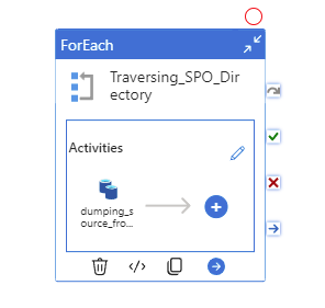
In the child pipeline pl_child_L1_copy_archive
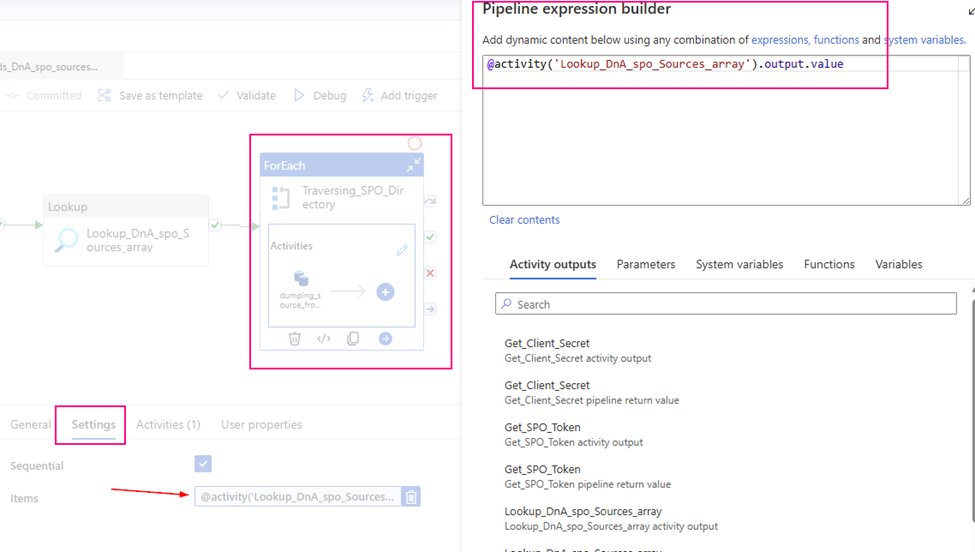
ForEach activity
Purpose: Iterate through each item in the file list.

Items: @pipeline().parameters.child_para_itemThe ForEach loop will iterate through each file, performing the following actions: copying the file to Azure Data Lake Storage and subsequently moving the processed file to the ‘Archive’ folder.
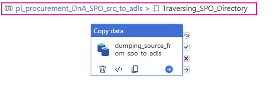
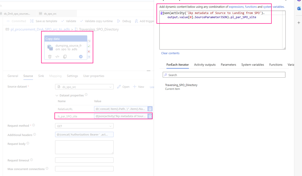
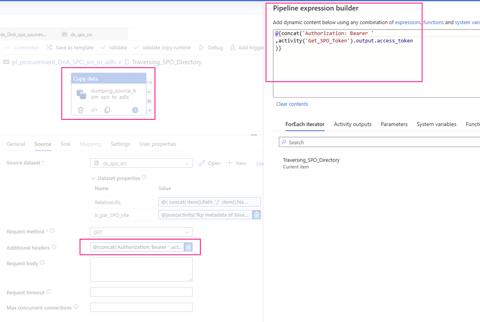
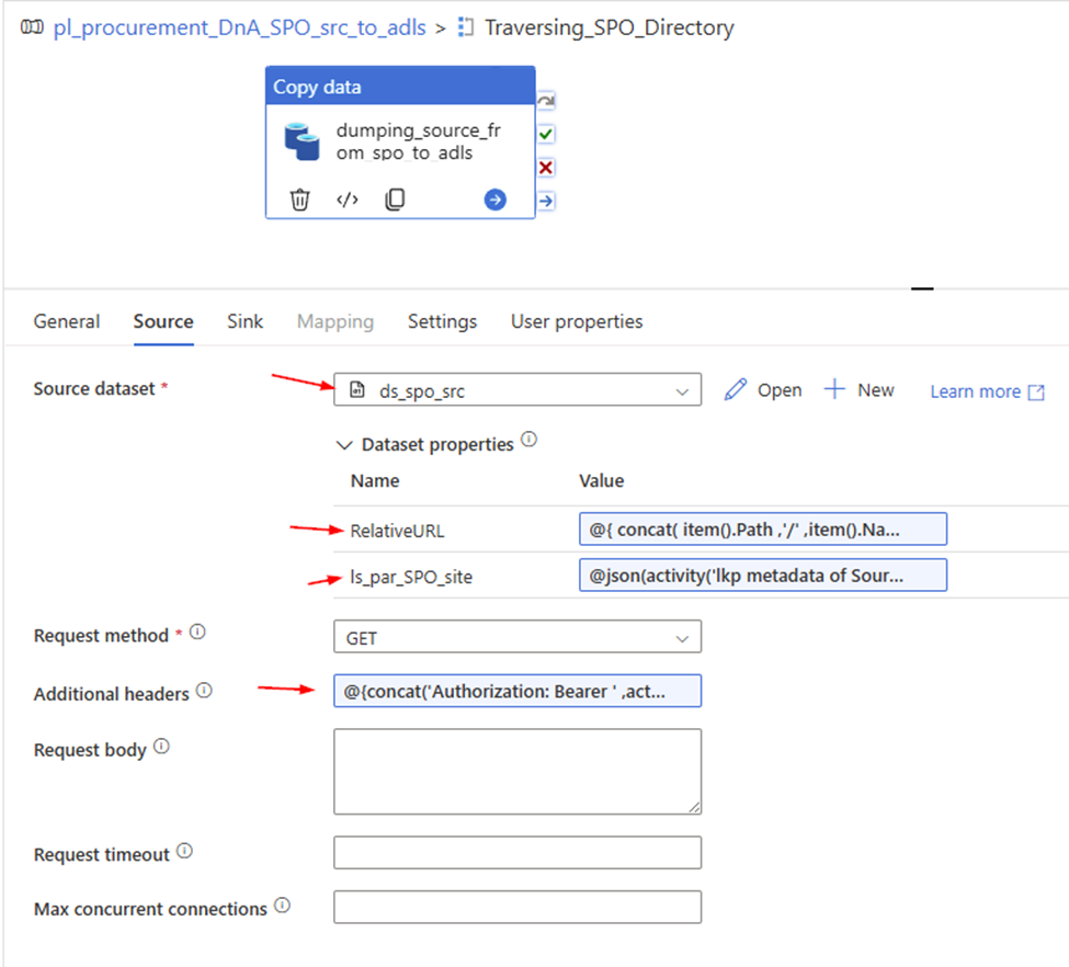
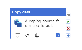
Step 23: Copy file to ADLS
Copy activity
purpose: copy file to ADLS one by one
Linked Service:
HTTP linked service, use Anonymous.

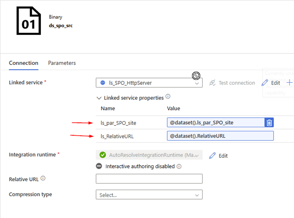
Source DataSet:
HTTP Binary dataset,

Sink Dataset
Azure Data Lake Storage Gen 2, Binary
Linked Services
Azure Data Lake Storage Gen 2

Sink dataset parameters:
ds_par_dst_path   string
ds_par_dst_fname   string
Step 24: Move processed file to “Archive” Folder
In the child pipeline pl_child_L1_copy_archive
Web Activity
Prupose: Move processed file from “Currrent” folder to “Archive” area.

URL:
@concat(
    'https://graph.microsoft.com/v1.0/drives/'
    , pipeline().parameters.child_para_FinanceID
    ,'/items/'
    , item().id
)

Method: PATCH

Body:
@json(
concat(
'{ "parentReference": {'
    , '"id": "'
    , activity('Create_rundate_folder_under_archive').output.id
    , '"}}'
))

Headers:
Authorization: @concat('Bearer ',activity('GetBearerToken').output.access_token)
Summary
The pipeline includes checks for folder existence to avoid redundant creation, especially in scenarios where the pipeline might be re-run. The IDs of relevant folders (“Archive” and the date-specific sub-folders) are retrieved dynamically throughout the process using filtering and list operations.
In essence, this pipeline automates the process of taking newly uploaded files, transferring them to ADLS, and organizing them within an archive structure based on the date of processing.
- Register an Azure AD Application (if not using Managed Identity), Grant the application the necessary Microsoft Graph API permissions, specifically Sites.Selected.
- Enable Managed Identity for your ADF (Recommended), Grant the ADF’s managed identity the necessary Microsoft Graph API permissions, specifically Sites.Selected. Enable Managed Identity for your ADF (Recommended), Grant the ADF’s managed identity the necessary Microsoft Graph API permissions, specifically Sites.Selected.
- Create a HTTP Linked Service in ADF, Base URL:
https://graph.microsoft.com/v1.0 - Web Activity to get an access token
URL:https://login.microsoftonline.com/<your_tenant_id>/oauth2/tokenMethod: POST
Body: (for Service Principal authentication)
JSON
{ “grant_type”: “client_credentials”,
“client_id”: “<your_application_id>”,
“client_secret”: “<your_client_secret>”,
“resource”: “https://graph.microsoft.com”
}
Authentication: None
Headers:Content-Type: application/x-www-form-urlencoded - get the Site ID
Web Activity to get the Site ID
URL:https://graph.microsoft.com/v1.0/sites/<your_sharepoint_domain>:/sites/<your_site_relative_path>
(e.g.,https://mainri.sharepoint.com:/sites/finance)
Method: GET
Authentication: none
header: “Authorization”@concat('Bearer ', activity('<your_get_token_activity_name>').output.access_token). - Web Activity to list the drives (document libraries)
URL:@concat('https://graph.microsoft.com/v1.0/sites/', activity('<your_get_site_id_activity_name>').output.id, '/drives')
Method: GET
Authentication: none
header: “Authorization”@concat('Bearer ', activity('<your_get_token_activity_name>').output.access_token). - Web Activity (or ForEach Activity with a nested Web Activity) to list the items (files and folders) in a specific drive/folder:
URL:@concat('https://graph.microsoft.com/v1.0/drives/', '<your_drive_id>', '/items/<your_folder_id>/children')(You might need to iterate through folders recursively if you have nested structures).
Method: GET
Authentication: none
header: “Authorization”@concat('Bearer ', activity('<your_get_token_activity_name>').output.access_token). - Copy Activity to download the file content
Source: HTTP Binary
Relative URL:@item()['@microsoft.graph.downloadUrl']
method: GET
Sink: Configure a sink to your desired destination (e.g., Azure Blob Storage, Azure Data Lake Storage). Choose a suitable format (Binary for files as-is). - Finally, Web Activity move processed file to Archive area.
URl: https://graph.microsoft.com/v1.0/drives/<your_drive_id>/items/<your_file_item_id>
Method; PATCH
Body:
@json(concat(
‘ { “parentRefence”: {‘, ‘ “id”:” ‘
, activity(‘Create_rundate_folder_under_archive’).output.id, ‘ “}}’))
Please do not hesitate to contact me if you have any questions at William . chen @ mainri.ca
(remove all space from the email account 😊)